|
|
 |
|
|
Realities of Exterior Wall Penetration: Oblique View
|
|
| |
|
|
| |
Oblique Perspectival View of penetration from Computer Model (see also animation from same model, below). This illustration indicates with not-so-subtle clarity how the engines and main wing spars (structural component of wings) present peril to the exterior shell of the building. The main wing spar and engines are far more massive and solid objects than the front of the fuselage itself.
|
|
 |
|
 |
|
|
|
|
|
|
Realities of Exterior Wall Penetration

|
|
| |
|
|
| |
Drawing 3: Elevation of 757-200 Superposition over actual opening created at Pentagon. Geometry (shape and dimensions) extracted forensically from photographs of the penetration available in the public domain. Both 757-200 fueselage (drawings courtesy of Boeing, Inc.) are to the same scale. As can be seen above, the aircraft fuselage cannot penetrate the wall of the pentagon without being tilted nose-down, which would create significant tracks in the lawn made by the engine cowlings and engines themselves – not to mention the fact that ground interference would tend to make the aircraft enter a headlong rotation, up-ending it against the building face. Photograph of site post-crash below shows no such marks or signs of interference. Please also note lack of damage that would clearly be inflicted by (a) main wing spars, (b) engines, (c) rear stablizer/rudder assy., etc.
|
|
| |
 hole in facade of wall. note undisturbed architectural and structural elements. hole in facade of wall. note undisturbed architectural and structural elements. |
|
 hole in facade of wall. note undisturbed architectural and structural elements. hole in facade of wall. note undisturbed architectural and structural elements.
|
|
|
| |
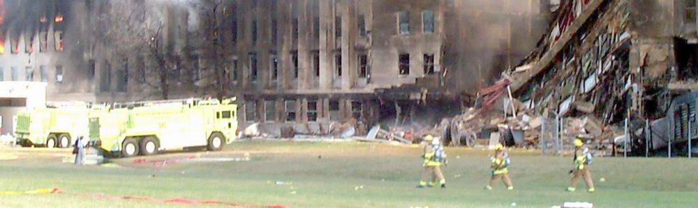 note the lack of significant disturbance of lawn in front of impact site. note the lack of significant disturbance of lawn in front of impact site.
|
|
|
|
|
|
|
|
|
|
|
Geometry of Impact: Structural Interference
|
|
| |
|
|
| |
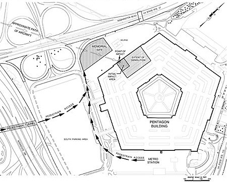
Drawing 4: Plan View 757-200 PENETRATION @ PENTAGON – PLAN
This drawing indicates the point of penetration of the 757-200 in the context of the official floor plan of the Pentagon, both at the same scale of course. The direction of travel of the aircraft is indicatd on the fuselage, above. Plan shows missing section of wall and interior structural elements. The drawing also indicates the impending collision between starboard wing leading edge and entry of building, which was left unscathed (see photographs). There are no marks or exterior damage from engines or from wing. The wing itself contains a rather massive beam, called the ‘main spar’ which is FAR stronger than are girders commonly used in skyscrapers. It is not only of comparable size – but is also heat treated and hardened to a higher specification – owing to the span across which it must function (approximately 125 ft) – a far greater span than can be found in the largest of skyscrapers.
See also: Animations at bottom of graphics section
Original drawings were made according to government and Boeing documents available in the public domain. See below for reference.
|
|
|
|
|
|
|
|
|
|
|
Penetration of Structural Building Elements by Boeing 757
5A: penetration at pentagon outer ring – outer layer of brick facade is not disturbed. no signs of damage |
|

5B: penetration at world trade center building 2. moment of aircraft successfully transferred to wingips -shearing through large )14" wide I-beams with 1"+ flange thickness. |
| |
|
|
INTERIOR @ Pentagon, ground floor, Ring ‘A’, typical
5C: EXTERIOR @ Pentagon, ground floor, Ring ‘A’, typical |
|
INTERIOR @ WTC Building 1, 83rd Floor
5D: EXTERIOR @ WTC Building 1, 83rd Floor |
above: structural details of exterior wall structures – comparing Pentagon and WTC Building 2 impact zones.
|
|
| |
|
|
| |
Figures 5A & 5B: Photographic evidence of Pentagon and WTC 2 respectively, showing damage from impact of similar planes. Penetration @ Pentagon Exterior wall does not correlate to distribution of mass or structural elements of Boeing 757. Single central hole is left behind, despite the lack of compressive strength of the 757 fuselage and the far greater strength/mass of wing and engine assembly.
|
|
|
|
|
|
|
|
|
|
|
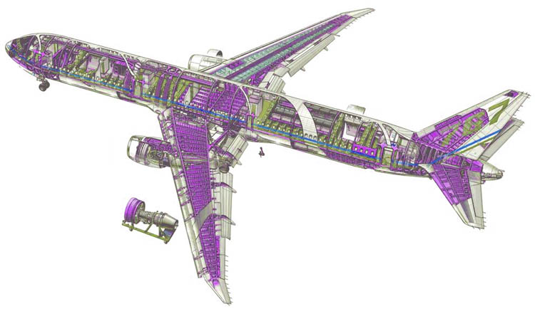
Structural Components of Boeing 757
|
|
| |
|
|
| |
Drawing 6, above: Structural view of Boeing 767 (nearly identical structurally to 757) showing primary and secondary structural elements (in purple). Supporting elements to main spar cage seen in wing, creating the overall stiffness required for the incredible structural loads demanded upon the 757’s wing structure. Please also note the relative lack of structural elements in the collapsible fuselage at front (the fuselage cannot bear the sorts of compressive load that the wing structure can).
|
|
| |
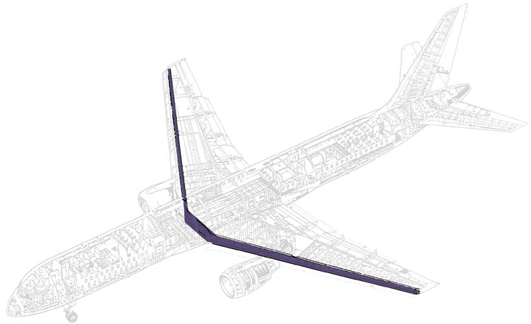
Drawing 7, above: Structural drawing (source: Boeing, Inc) indicating continuous main wing spar. The main wing spar is supported by horizontal ribs and other members, welded to it forming an extremely rigid cage, capable of withstanding hundreds of tons of compressive force over a small area. Please see drawing 6, above, to see the context and construction of this assembly.
|
|
| |
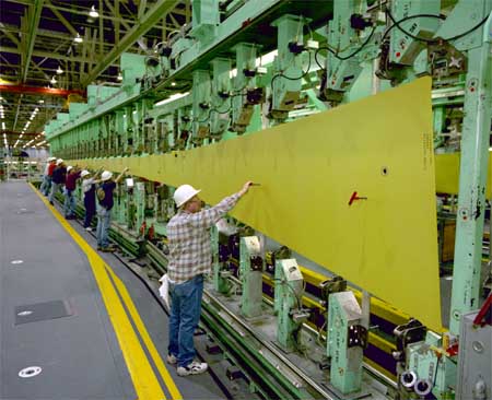
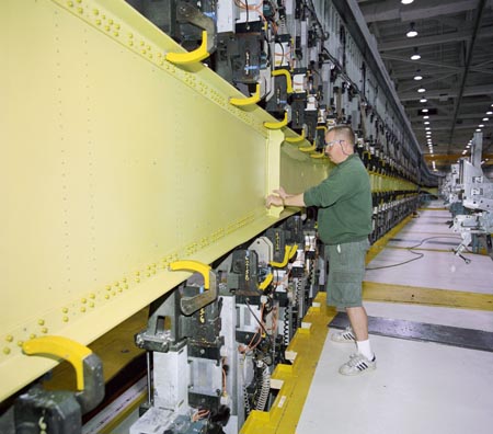
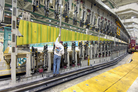
Photographs of layup of a 757 main wing spar at Boeing, Inc. The main wing spar is far and beyond the most structurally critical component in most airplanes. It is primarily responsible for the structural integrity of the aircraft and supports most of weight of the aircraft during flight. It could be fairly said that the main wing spar, along with it’s integral structural supports, is many fold stronger than the structure of most high rise buildings. See illustration 5B if you have any doubt in this matter.
|
|
|
|
|
|
|
|
|
|


 List of Members
Log in
List of Members
Log in